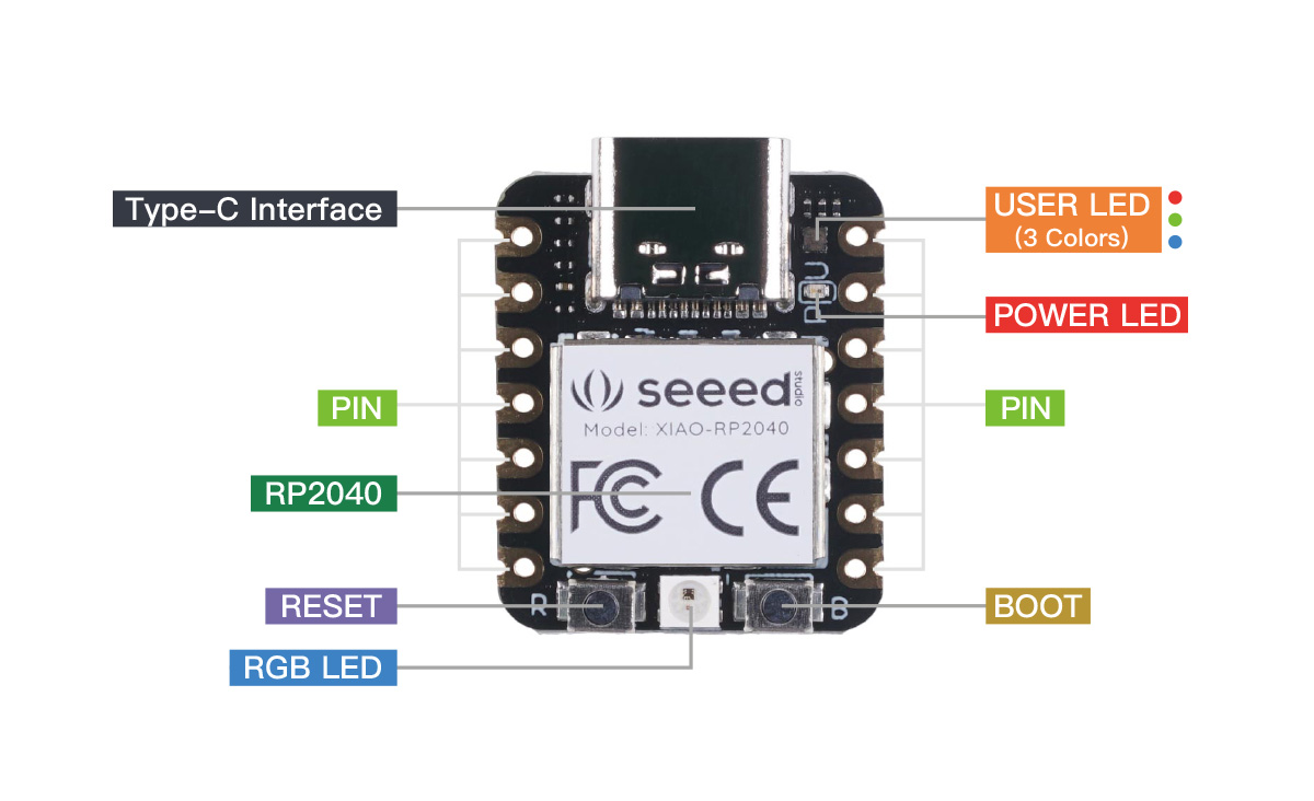
Pin Map
Pin Map
| XIAO Pin | Function | Chip Pin | Description |
|---|---|---|---|
| 5V | VBUS | Power Input/Output | |
| GND | |||
| 3V3 | 3V3_OUT | Power Output | |
| D0 | Analog | GPIO26 | GPIO, ADC |
| D1 | Analog | GPIO27 | GPIO, ADC |
| D2 | Analog | GPIO28 | GPIO, ADC |
| D3 | Analog | GPIO29 | GPIO, ADC |
| D4 | SDA | GPIO6 | GPIO, I2C Data |
| D5 | SCL | GPIO7 | GPIO, I2C Clock |
| D6 | TX | GPIO0 | GPIO, UART Transmit |
| D7 | RX,CSn | GPIO1 | GPIO, UART Receive,CSn |
| D8 | SCK | GPIO2 | GPIO, SPI Clock |
| D9 | MISO | GPIO4 | GPIO, SPI Data |
| D10 | MOSI | GPIO3 | GPIO, SPI Data |
| Reset | RUN | RUN | |
| Boot | RP2040_BOOT | Enter Boot Mode | |
| CHARGE_LED | VCC_3V3 | CHG-LED_Red | |
| RGB LED | GPIO12 | RGB LED | |
| USER_LED_R | GPIO17 | User-controlled red RGB LED pin | |
| USER_LED_B | GPIO25 | User-controlled blue RGB LED pin | |
| USER_LED_G | GPIO16 | User-controlled green RGB LED pin |
Enter Bootloader Mode
Sometimes the Seeed Studio XIAO RP2040 port may disappear when user programming process fails. We can solve this problem by the following operation:
- Long press the "B" button.
- Connect the Seeed Studio XIAO RP2040 to your computer.
- The computer will appear a disk driver.
At this point, the chip enters Bootloader mode and the burn port appears again. Because the RP2040 chip has two partitions, one is the Bootloader and the other is the user program. The product will burn a bootloader code in the system memory when it leaves the factory. We can switch modes by performing the above steps.
Reset
If you want to reset the Seeed Studio XIAO RP2040, perform the following steps:
- Connect the Seeed Studio XIAO RP2040 to your computer.
- Press the "R" pins once.
Please note: The behavior of the built-in programmable Single-colour LEDs (They are red, blue and green) are reversed to the one on an Arduino. On the Seeed Studio XIAO RP2040, the pin has to be pulled low to enable.